The link to the article I wrote for the Midwest VHF and UHF Society newsletter on how I repaired a Mirage B-5030-G 144-148 MHz Power Amplifier is available on the link below.
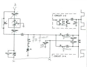
I bought a Mirage B-5030-G used a couple years ago and when I put it in it had an Input SWR of 1.8 to 1, which was at the top end of its specs. About January of 2025, the SWR jumped to 3 to 1 and the amp became unusable. To fix it I started looking for a schematic but could not find one. After opening it up I discovered the board had a place for a predriver (no parts installed) that was bypassed with a piece of coax. I did find a schematic for the Mirage B-3030. For comparison the B-3030 is rated 250 mW to 30 Watts input, where the B-5030 is rated 1 Watt to 60 Watts input. Both are rated for 300 Watts out. I therefore believe that both amps use the same circuit board, with the B-5030 having the predriver section bypassed. That makes the B-3030 schematic useful for diagnosing B-5030 issues. Here is a jpg of what I believe the input to the B-5030-G looks like.
The primary failure of my amp was a 750 PF Capacitor (approx.. C27 on the B-3030 Schematic or C26 in my markup below). Instead of the resistor network (along with L8 and C28) that is behind C27, there is a variable capacitor to ground from C27. That variable capacitor along with C27 and the strip line “tunes” the input. Diagnoses was done with a VNA.
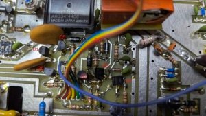
After putting it back in service the Fault LED keep lighting up. Discovered using a VNA that the SO239 output connector was also flakey, so it had to be replaced as well as the input connector. Then I found that the Zener diode ZD1 was bad (0.5 VDC instead of 3.3 VDC) along with Q3, which failed short. The Zener caused the the SWR detection to be more sensitive than it should have been. The transistor failure prevented the amp from being taken offline when faults were detected.
The Mirage B-3030 schematic is at: https://www.repeater-builder.com/other-mfrs/pdfs/mirage-b-3030g.pdf Below is an image of what my amplifier’s input to the power transistors looks like. Your’s might be different. There are some minor changes in the output as well. L1 and L7 are to pass DC to the base of the power transistors through the TR relay..
Part Identification:
The article pages out of the Midwest VHF and UHF Society Newsletter: Anomalous-Propagation-September-2025 are at this link:
Article on Mirage B-5030-G Repair from Anomalous Propagation September 2025
Follow-up on Mirage repair December 2025 issue of Anomalous Propagation